

Hertz theory guide
Hertzian Contact Stress in Rolling Bearings
Understand effective material and curvature properties, contact-patch size, and maximum Hertz pressure in rolling contacts.
Why rolling contacts develop high pressure
A rolling element and raceway appear to meet at a point or line before loading. Elastic deformation creates a small contact patch that carries the rolling-element load. Because the patch is small, local pressure can reach the gigapascal range even when the applied force seems modest.
Ball-bearing contacts are generally elliptical. Roller contacts are closer to line contacts but require edge and profile corrections. The circular point-contact model below is a useful introduction, not a complete bearing-contact model.
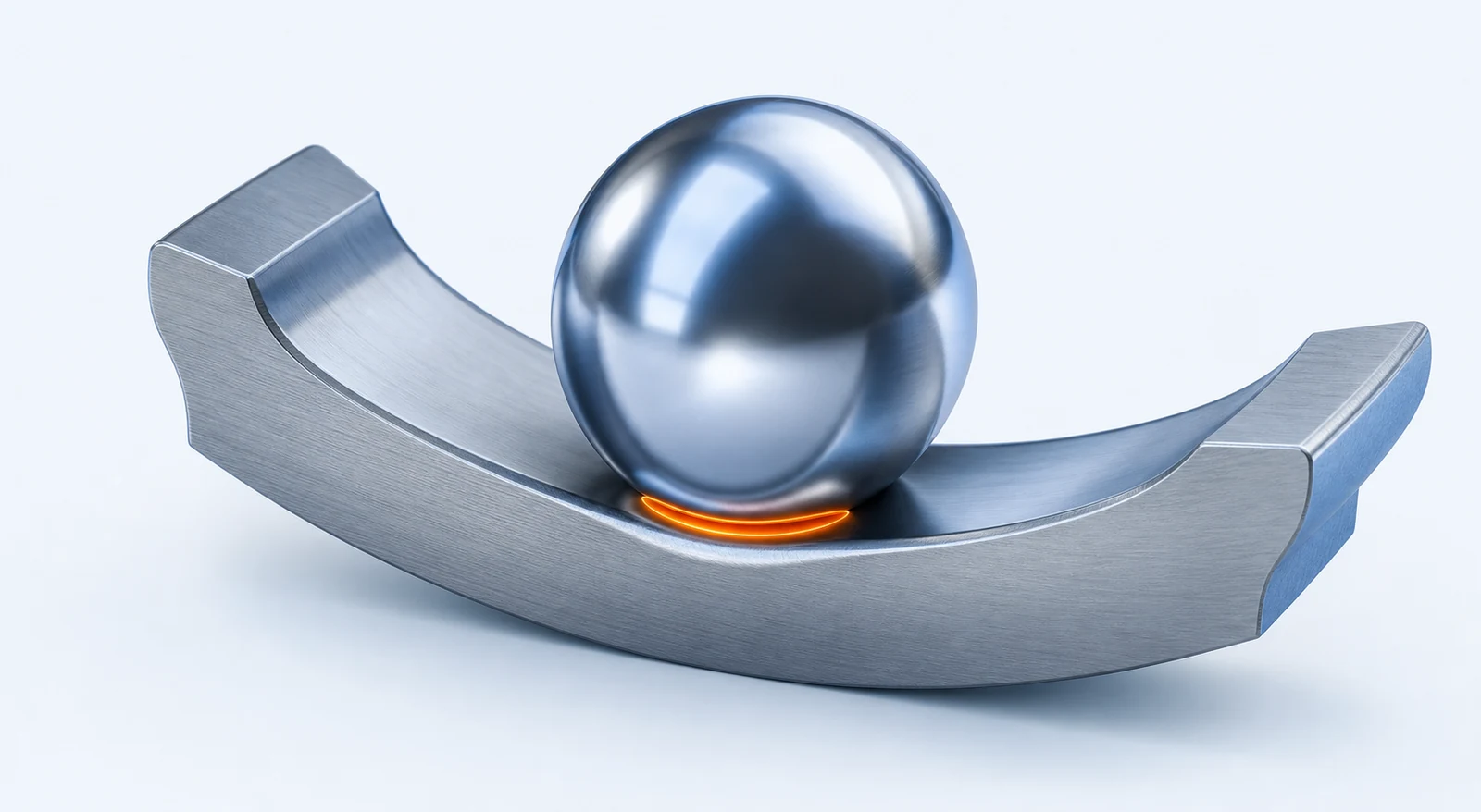
Use the equations below only for smooth, frictionless, elastic bodies with a circular contact patch. A ball-to-raceway contact is normally elliptical and requires the two principal curvatures, elliptical semi-axes, and the actual raceway geometry.
Effective material and curvature properties
Here, E is Young's modulus, ν is Poisson's ratio, and R describes surface curvature. The scalar R* equation applies to the circular-contact simplification. Convex and concave surfaces require opposite curvature signs; a real ball-to-raceway calculation resolves curvature independently in two principal directions.
Simplified circular contact
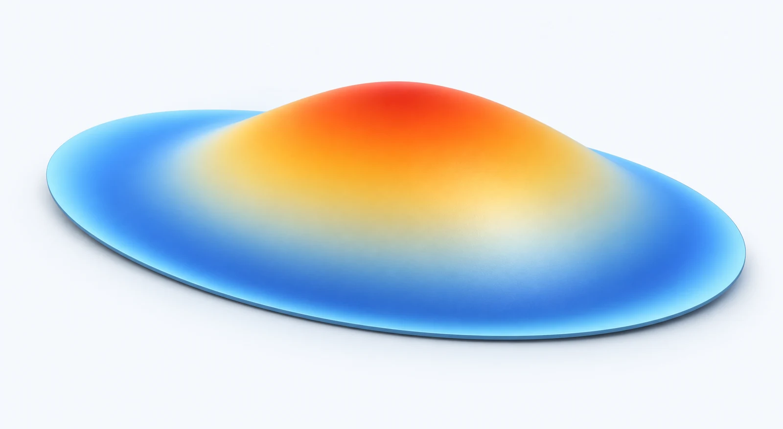
Pressure decreases from p0 at the centre to zero at the contact edge. Subsurface shear stresses also develop below the surface, which is why a bearing analysis should consider more than the peak surface pressure alone.
Worked example
For two steel bodies with E = 210 GPa and ν = 0.30, the reduced modulus is approximately 115.4 GPa. With F = 1,000 N and R* = 10 mm:
- Contact radius: a ≈ 0.402 mm
- Maximum pressure: p0 ≈ 2.95 GPa
Standards and further reading
- K. L. Johnson, Contact Mechanics, Cambridge University Press, 1985.
- NASA TP-2473 — Hertzian Contact in Two and Three Dimensions
- ISO 16281:2025 — Bearing-specific load distribution and rating-life context
This educational guide does not reproduce the standards. Its equations and examples have been checked against the cited public references, but the guide has not been independently certified or reviewed for your application. Use the current standard, manufacturer data, and an appropriate engineering review for final bearing selection.
Apply the method
Run a complete bearing calculation
Model bearing geometry, loading, lubrication, life, load distribution, and contact stresses in one workflow.