

Calculator quick start
How to Use the BearingSolve Calculator
Start with the built-in example, replace it with your bearing data, and understand when the displayed results need to be recalculated.
Before you begin
Collect the internal bearing geometry and the operating data for the condition you want to evaluate. Catalogue boundary dimensions alone are generally not enough for a representative calculation.
- Internal geometry: pitch diameter, rolling-element dimensions and count, contact angle, raceway conformity or profile, and clearance.
- Materials: raceway hardness, elastic modulus, and Poisson ratio.
- Lubrication: lubricant viscosity at 40 °C and 100 °C, operating temperature, and contamination condition.
- Operating point: speed, rotating ring, forces, moments, and the reliability required for the life result.
For a duty cycle with several speeds or loads, calculate each condition separately and combine its contribution using an appropriate duty-cycle method.
Run the example first
The calculator opens with a complete example for a single-row deep-groove ball bearing. It includes bearing geometry, standard steel properties, grease lubrication, a speed of 700 RPM, and a 1,000 N radial load.
- Open the calculatorLeave the example values unchanged for your first run.
- Run CalculationWait while the result cards and plots are prepared.
- Check the status“Results up to date” confirms that the results match the inputs.
Replace the example with your inputs
Work through the input sections from top to bottom. Changing the bearing type updates which dimensions and load components are available.
- Bearing Type & Position Choose the bearing design and add the X-axis position of each bearing represented by the model.
- Geometry Enter pitch diameter, rolling-element size and count, raceway geometry, and internal clearance. Use the inline geometry preview to check the model.
- Material Confirm raceway hardness, elastic modulus, and Poisson ratio for both rings and the rolling elements.
- Lubrication Select the lubricant and cleanliness condition, then enter its kinematic viscosity at 40 °C and 100 °C.
- Loading & Condition Choose the rotating ring and enter speed, operating temperature, axial force Fx, radial forces Fy and Fz, and the supported moments.
For example, geometry is entered in millimetres, forces in newtons, moments in Nmm, and material elastic modulus in MPa.
Geometry field reference
| Input | How it is used |
|---|---|
| Pitch diameter (Dpw) | Diameter through the centres of the rolling elements. |
| Rolling-element diameter (Dwe) | Ball or roller diameter used in the internal geometry. |
| Effective length (Lwe) | Effective raceway contact length for a roller bearing. |
| Rolling-element count (Z) | Number of balls or rollers in one row. |
| Contact angle | Nominal unloaded angle between the contact normal and the radial plane. |
| Raceway radius or conformity | Defines how closely the raceway groove conforms to the rolling element. |
| Internal clearance | Initial radial or axial freedom before the operating load is applied. |
| Row distance | Axial separation of the two rows in a double-row bearing. |
Material and lubrication details
- Use the actual elastic modulus and Poisson ratio when the rings or rolling elements are not standard bearing steel.
- The rating-life model expects hardened raceways. Review the displayed validity note when raceway hardness is below 58 HRC.
- The calculator derives operating viscosity from the two reference viscosities and temperature. Cleanliness contributes to the contamination factor eC and, together with viscosity, to aISO.
Understand loads and coordinates
BearingSolve uses X as the bearing axis. Confirm the direction and sign of every load before entering it, especially for a model containing more than one bearing.
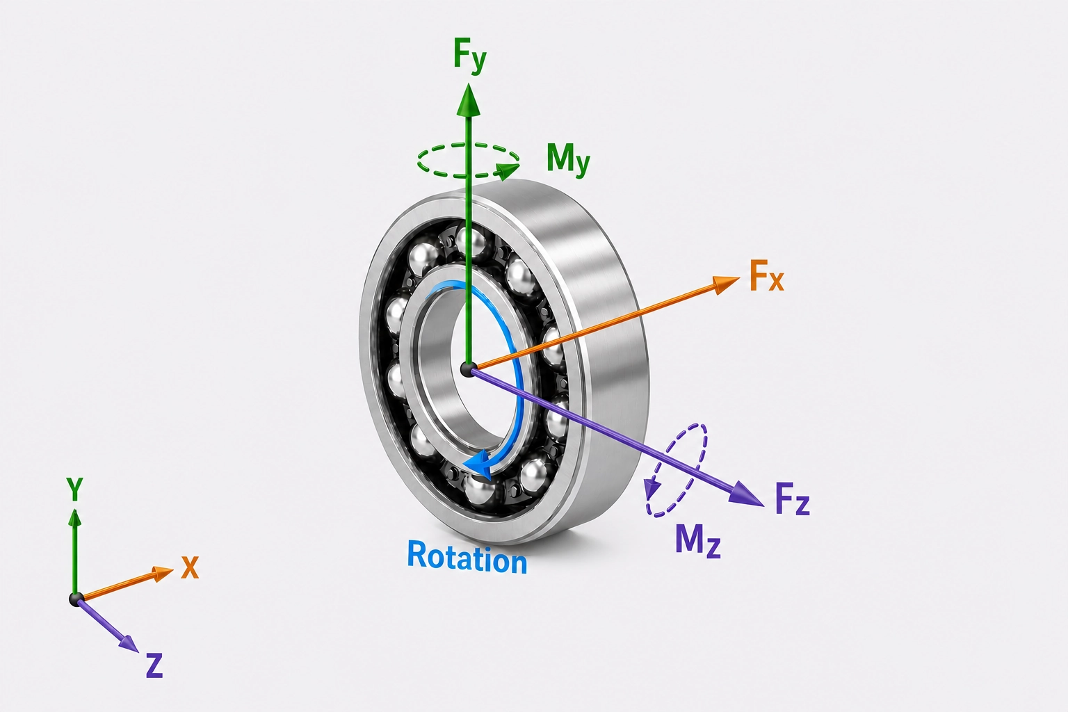
| Field | Meaning |
|---|---|
| Bearing position X | Axial location of each bearing along the modeled shaft. |
| Fx | Axial force along the bearing axis. |
| Fy, Fz | Radial force components perpendicular to the bearing axis. |
| My, Mz | Bending moments about the radial axes. |
| Rotating ring | Identifies whether the inner or outer ring rotates relative to the load. |
On a wide screen, the preview updates with valid geometry inputs. It can reveal an incorrect dimension or bearing arrangement before you calculate.
Fix an input that prevents calculation
Run Calculation is disabled while an input is invalid. An exclamation icon identifies the section that needs attention; open that section to see the field-level message.
- Check that required values are present and within the displayed limits.
- Check that rolling-element dimensions are compatible with the pitch diameter.
- After changing the bearing type, review fields that were enabled, disabled, or recalculated for that design.
After editing a valid model, the status changes to “Changes ready to calculate.” Run the calculation again before using the results.
Read the results
The first result card summarizes the main calculated values:
| Result | What it represents |
|---|---|
| C0, Cdyn, Cu | Static, dynamic, and fatigue load ratings. |
| Basic life | Rating life in millions of revolutions and operating hours. |
| Modified life | Rating life including the displayed life-modification factors. |
| pmax | Maximum calculated rolling-contact pressure in MPa. |
| Maximum contact angle | Largest loaded rolling-element contact angle in the bearing. |
| Viscosity ratio and eC | Lubrication-condition ratio and contamination factor used for modified life. |
| aISO | Life-modification factor calculated from lubrication and contamination. |
| System ratings | Combined rating values shown when the model contains multiple bearings. |
Use the plots to find the critical contact
- Contact Stress 3D, Cartesian, and Polar: compare the pressure around the rolling elements and locate the most heavily loaded zone.
- Contact Angle: inspect how the loaded contact angle varies around the bearing.
- Roller Stress: examine how line-contact stress varies across roller sections.
- Subsurface and shear-stress plots: inspect stress below the contact, including maximum and orthogonal shear stress.
Plots render as they approach the viewport, so scroll through the results before assuming a chart is missing. Expand a plot when you need a larger view.
Compare results with the applicable standard, manufacturer limits, required service life, and an appropriate engineering review for the application.
Settings, files, and saved calculations
- Reliability
- Choose 90% (L10) through 99% (L1). Higher reliability normally produces a lower reported rating life for the same operating condition.
- First rolling-element angle offset
- Rotate the first rolling element by up to ±30°. This can reveal sensitivity to the rolling-element orientation relative to a radial load.
- Roller section count
- Choose 11 to 71 calculation sections for roller bearings. More sections give finer resolution across the roller but require more calculation work.
- Export inputs
- Download the current inputs as a reusable BearingSolve JSON case file. Results are not included.
- Import inputs
- Replace the current inputs with a BearingSolve case file and run it automatically.
- Save calculation
- Save the current inputs and results to your account after a calculation has completed. Sign-in is required.
Troubleshooting
- Run Calculation is disabled
- At least one input is incomplete or outside its accepted range. Open the section with the exclamation icon and correct its field-level message.
- A load field cannot be edited
- The selected bearing type or arrangement does not support that load component. Review the bearing type before changing other inputs.
- Results are marked as out of date
- An input changed after the last successful calculation. Run the model again before using, exporting, or saving conclusions based on the results.
- Life or pressure is unexpected
- Recheck units, force directions, bearing position, rotating ring, clearance, contact angle, lubricant viscosity, temperature, and cleanliness. Compare one change at a time against the example or a known reference case.
- An imported file is rejected
- Use an unedited JSON file produced by Export inputs. Import replaces the current case, so export your work first if you need to preserve it.
- Save calculation is unavailable
- Sign in and complete a successful calculation. Saved calculations include the current inputs and results; exported case files contain inputs only.
Ready to calculate?
Start with the example
Run the default model once, then build and verify your case one input section at a time.